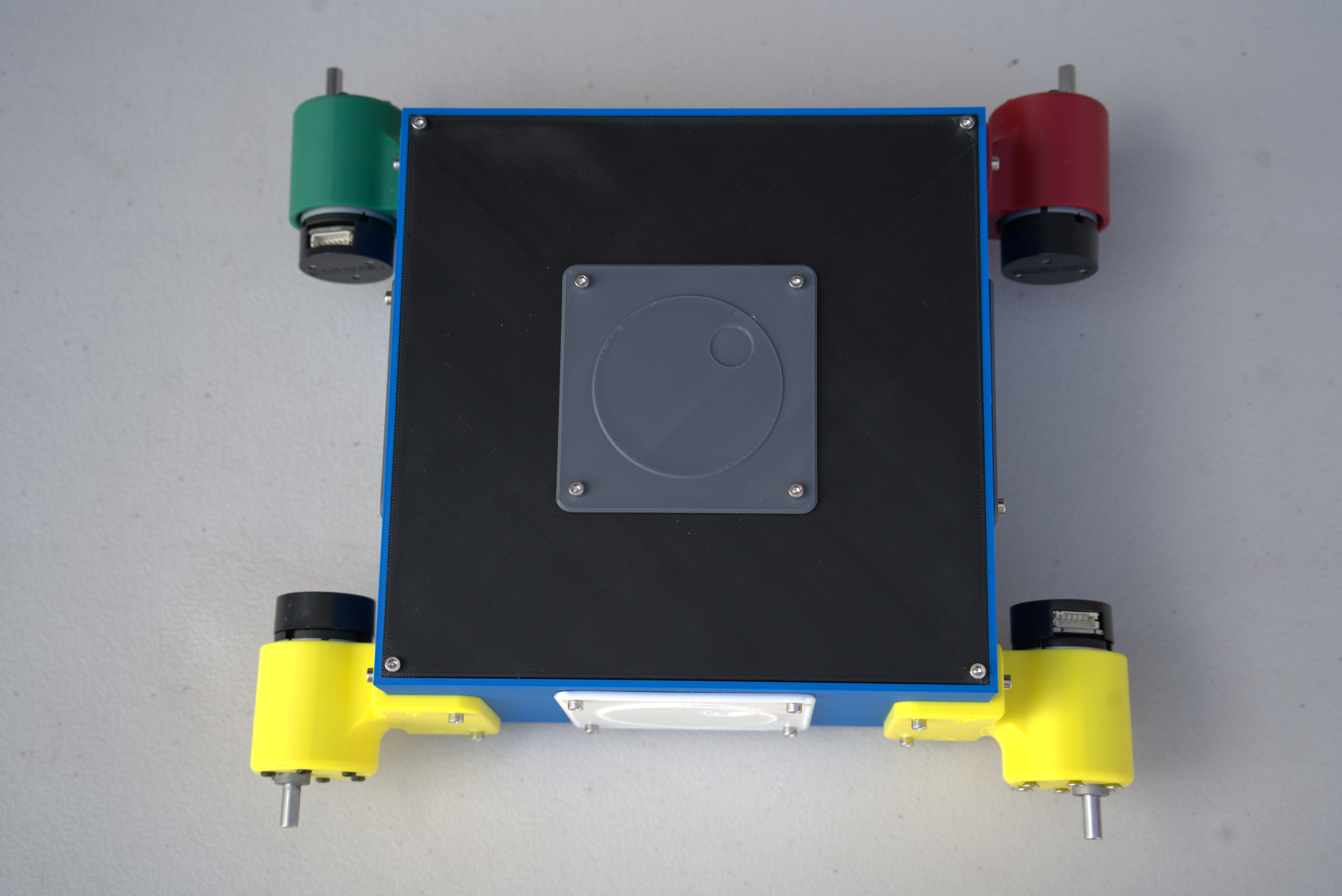
Assembly Instructions
A parallel assembly video is also available.
Step 1: Heat-Set Inserts
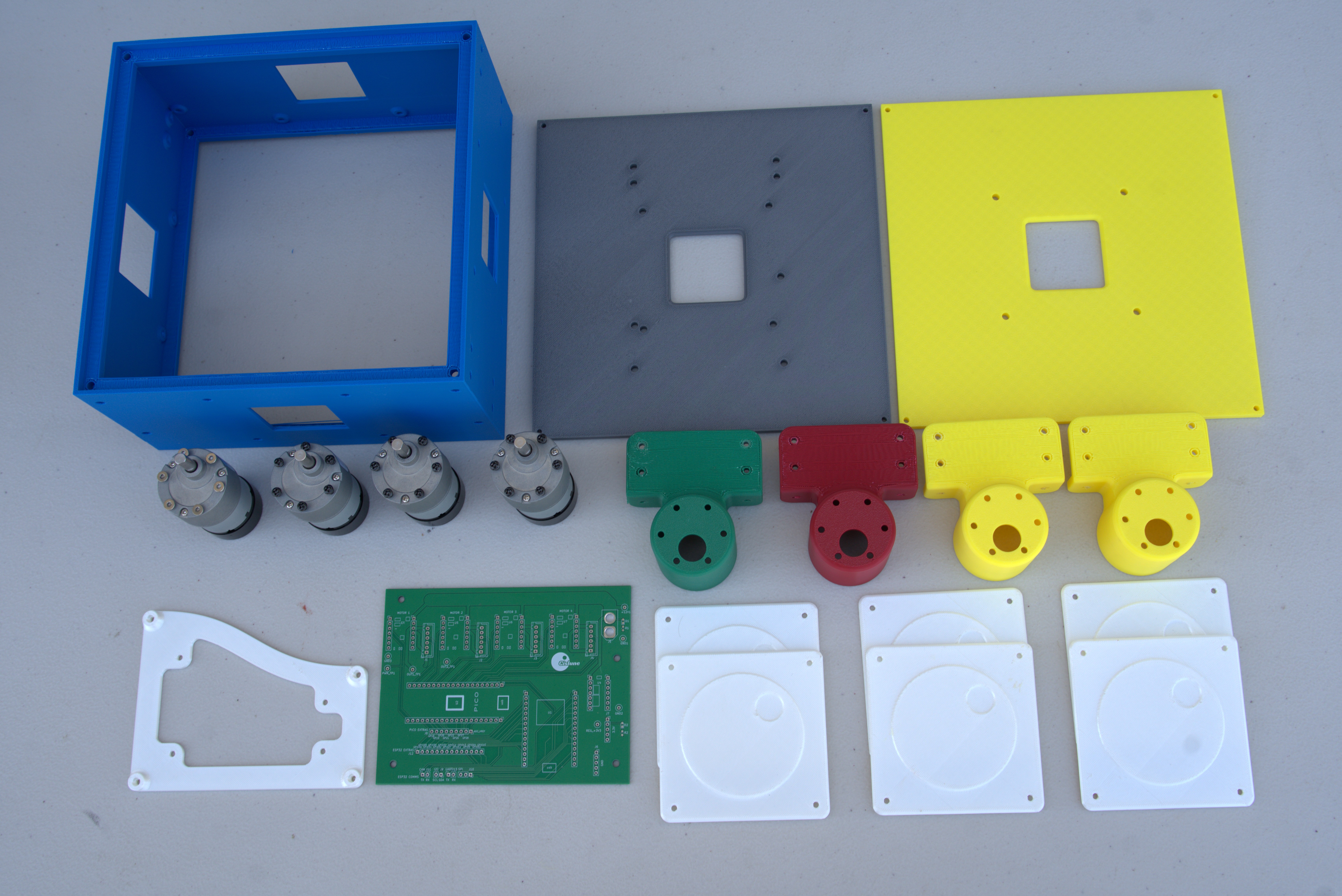
First, add heat-set inserts to the parts shown below.
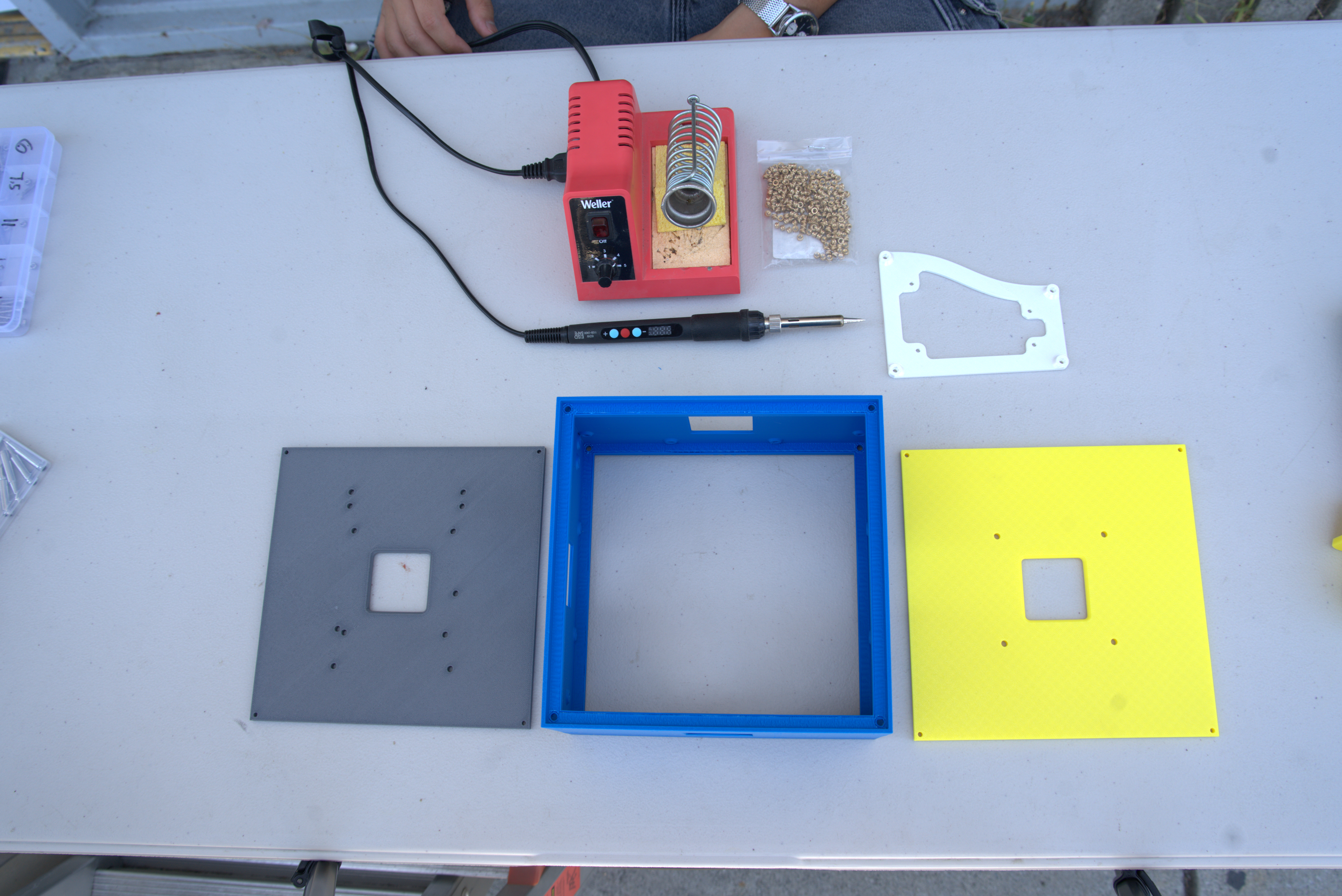
Most heat-set insert placement is straightforward. Every hole measuring 4.2–4.3 mm is intended to receive an insert. The pictured parts do not show them, but newer CARVE Core revisions should have indicator rings around the insert locations. A ring identifies both the location and the insertion side. This distinction is important on the bottom base plate.
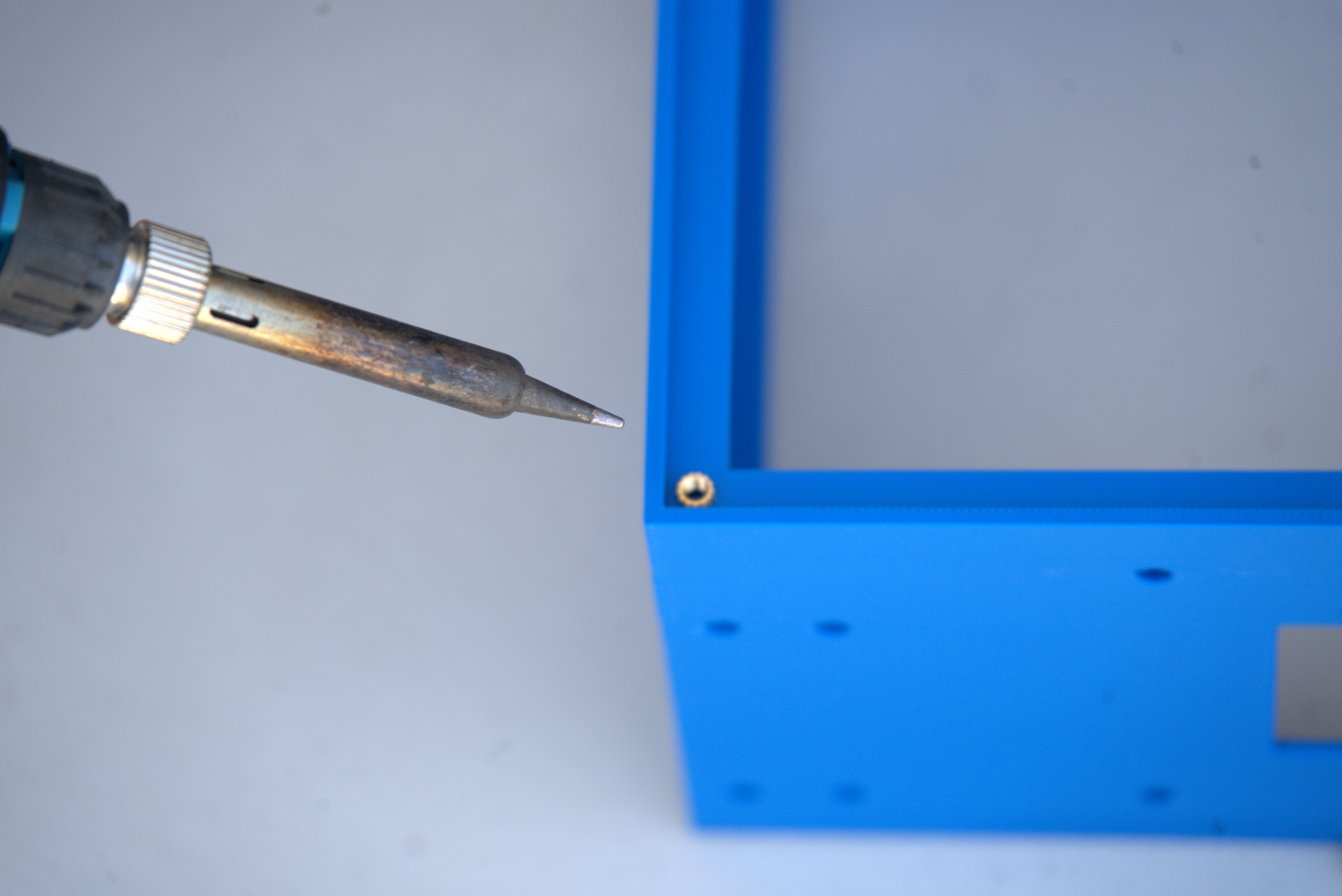
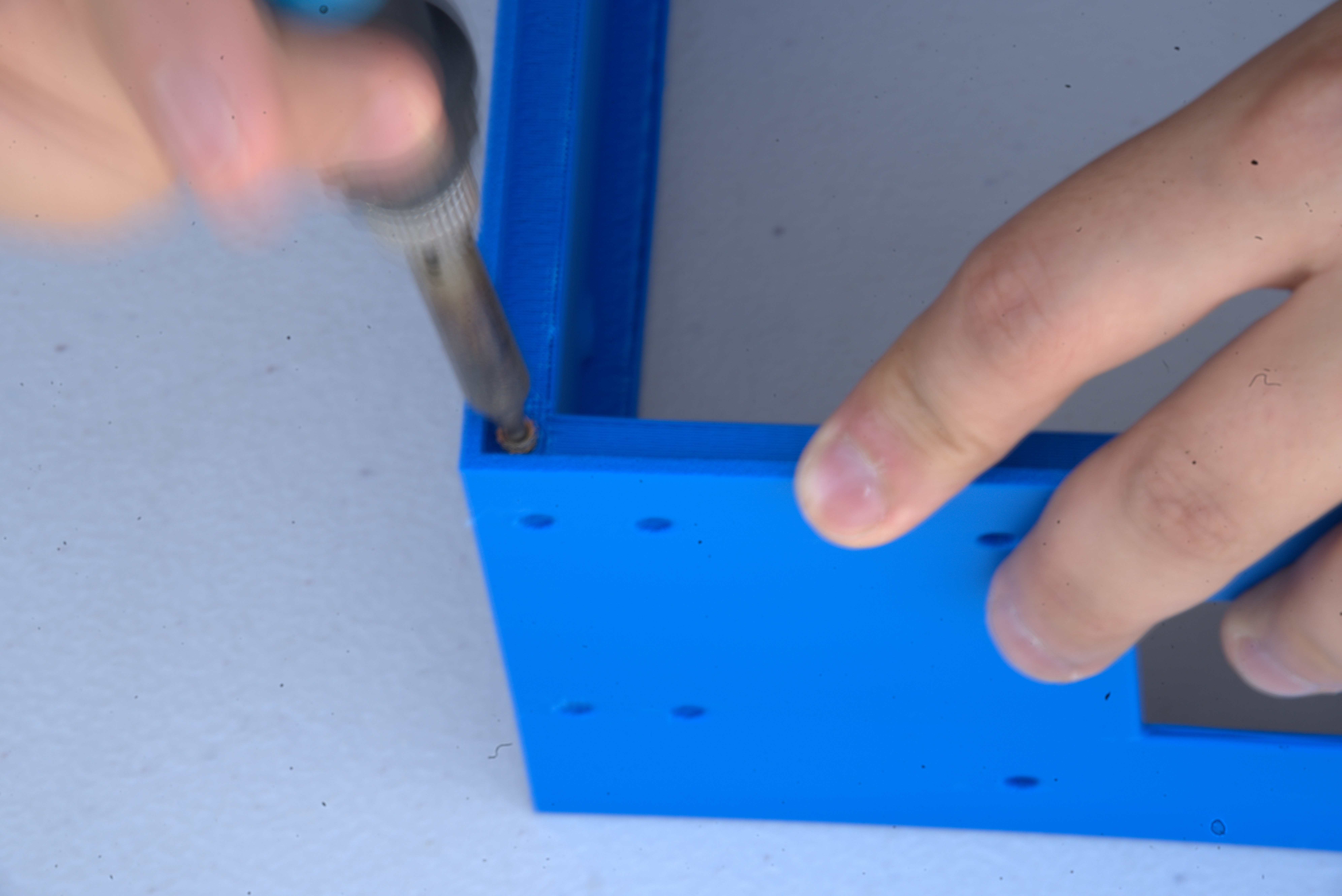
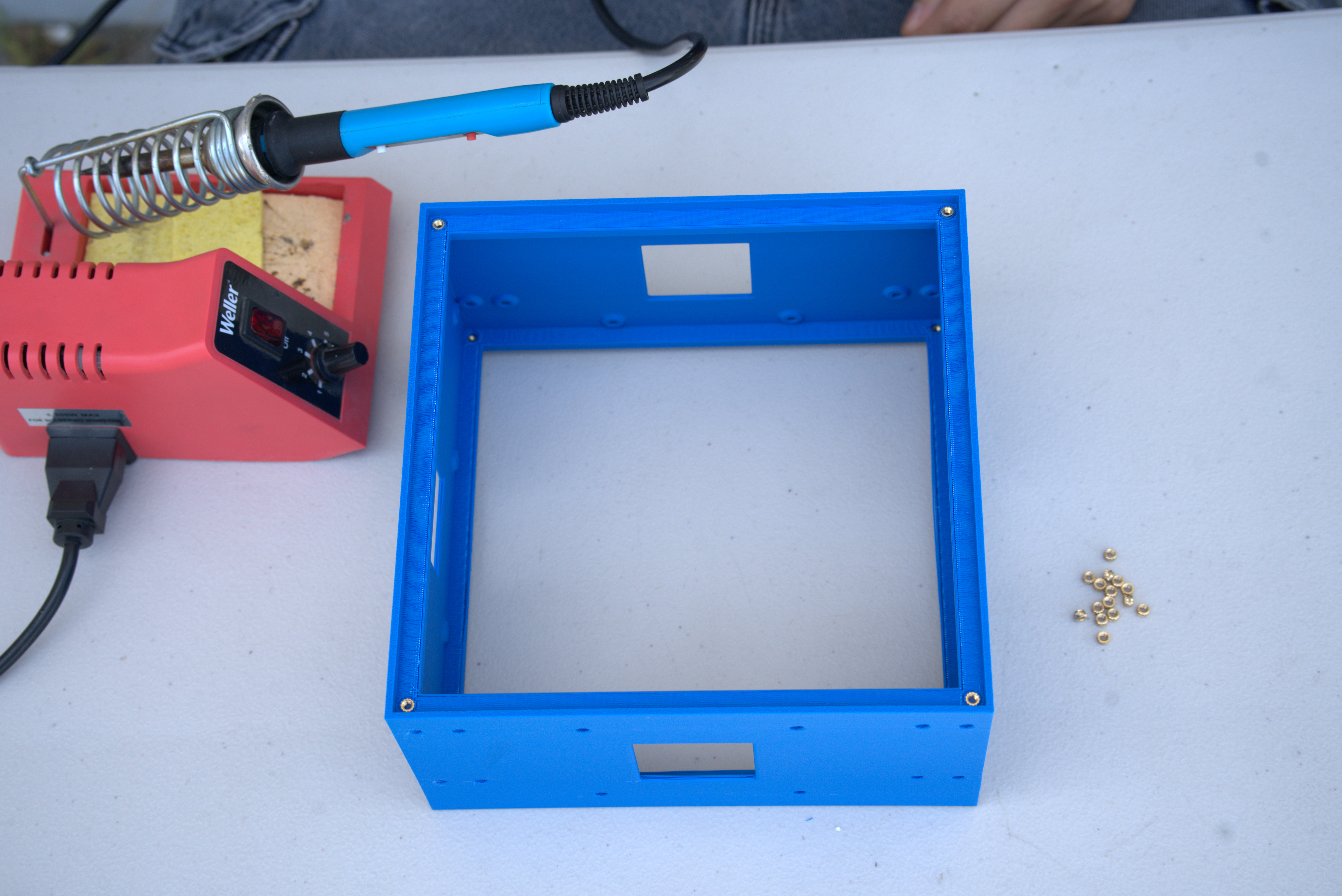
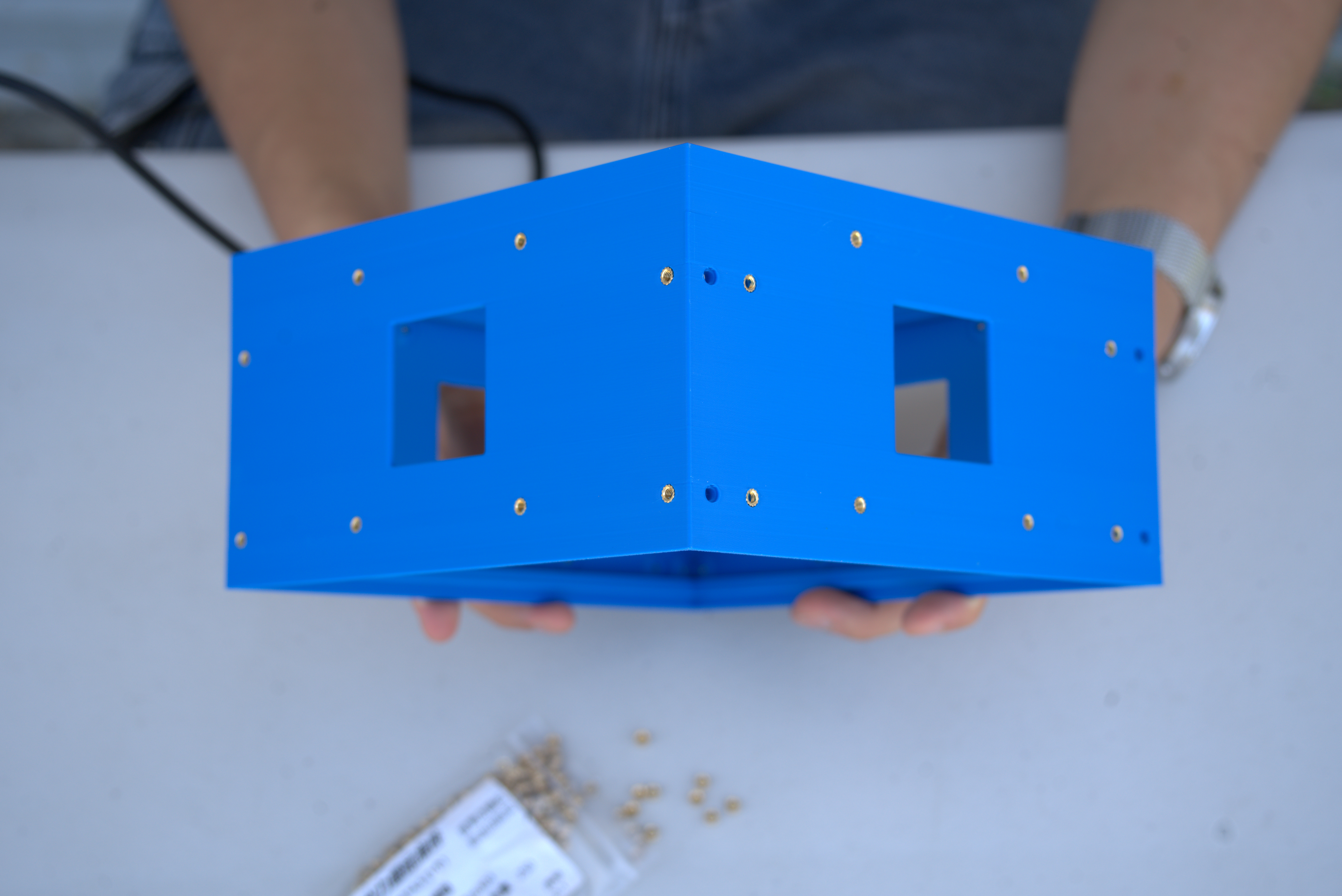
The center chassis requires inserts on the top, bottom, and sides. Each motor-mounting position needs only the four outer inserts rather than all six available locations.
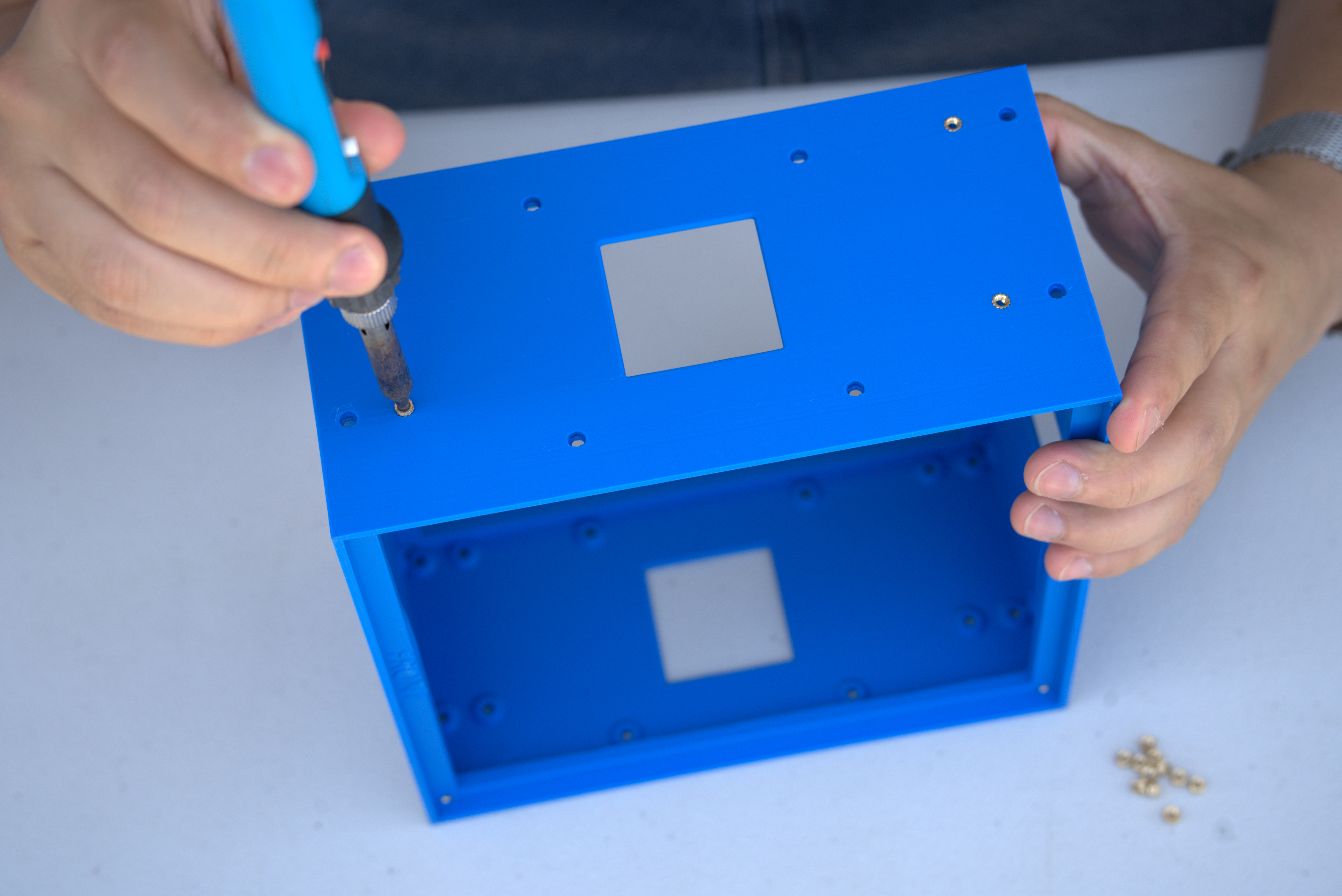
Next, add the heat-set inserts to the top plate.
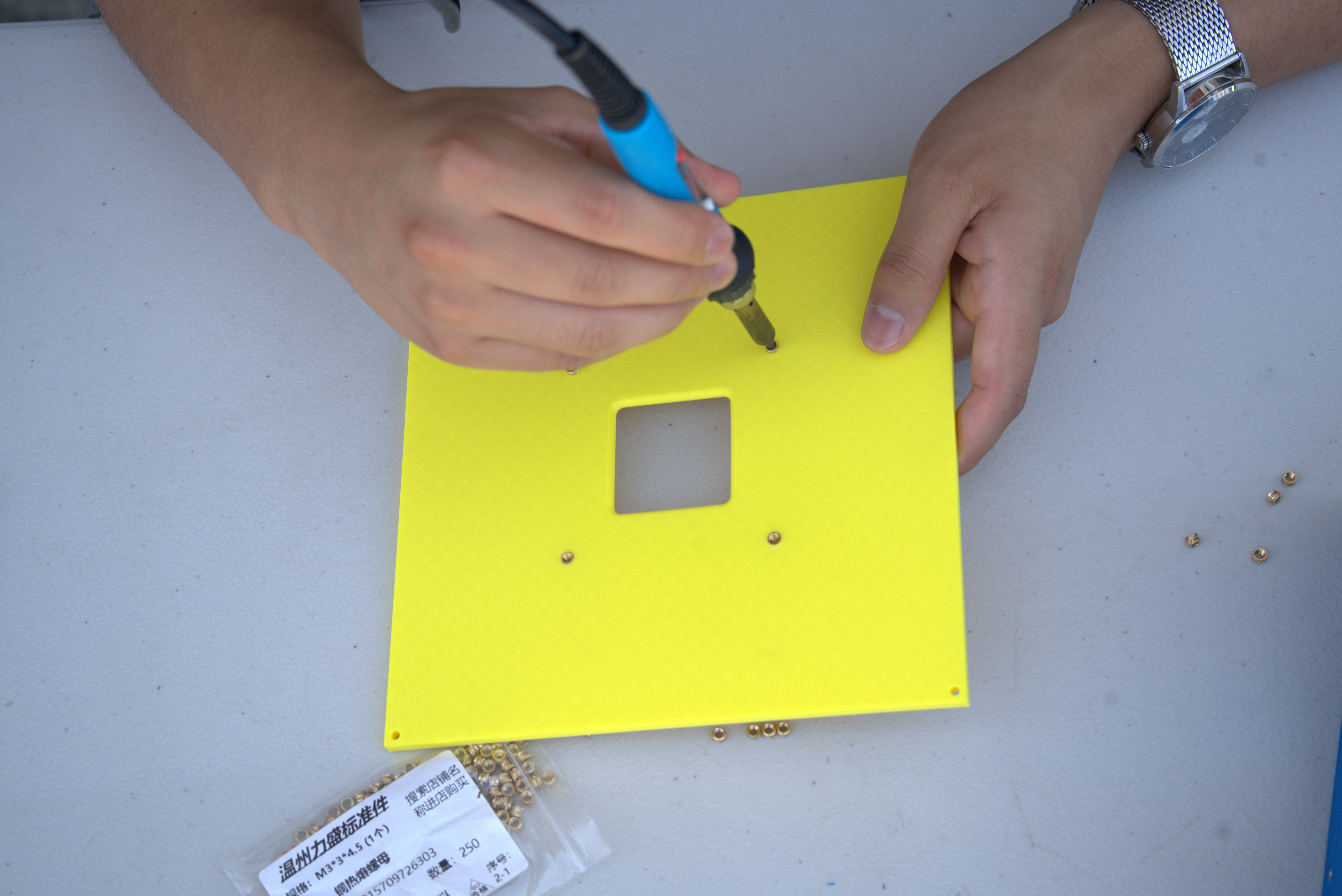
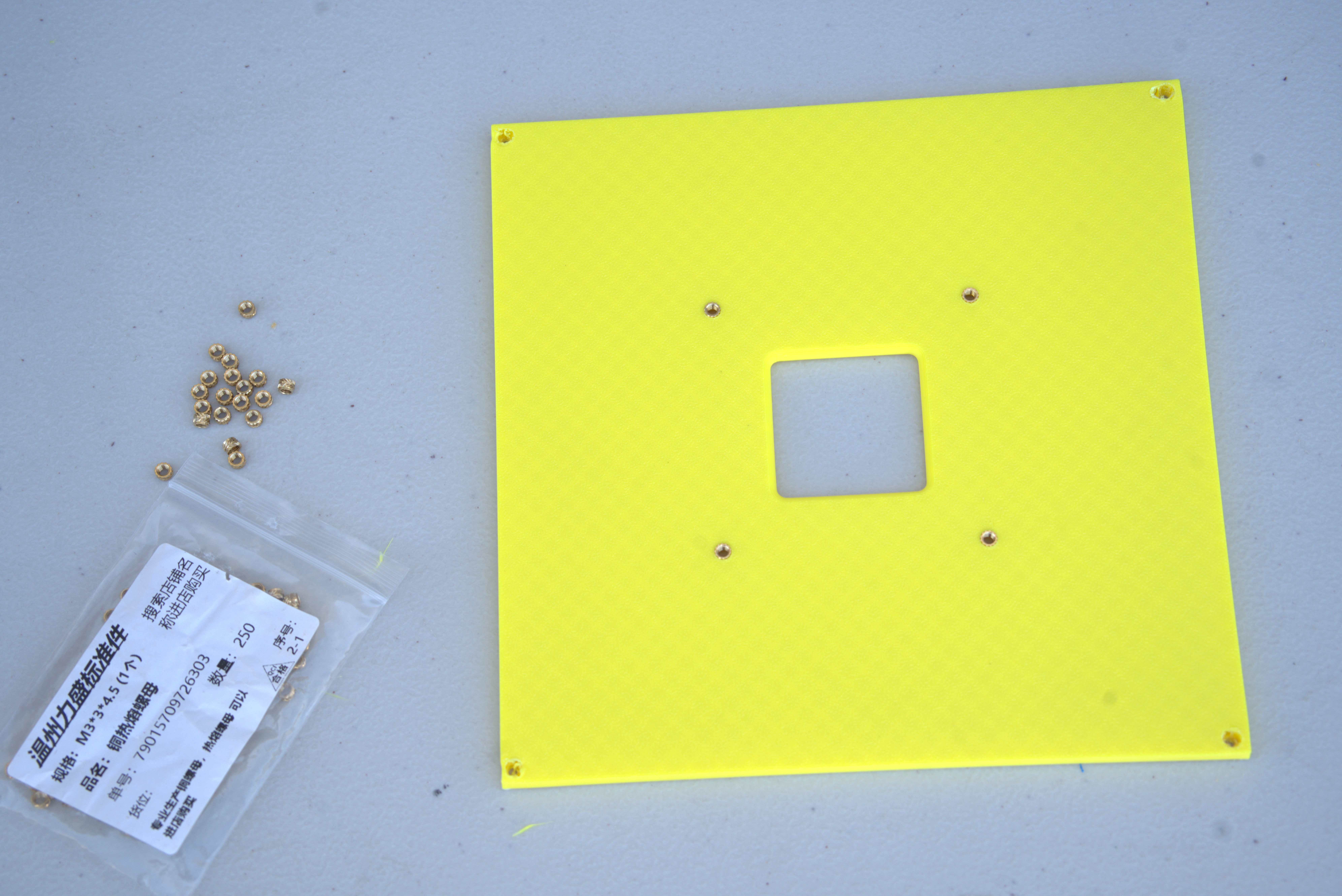
The bottom plate is slightly more involved. The module inserts belong on one side and the remaining inserts on the other. Their orientation matters because the PCB mount is asymmetrical. If the model has indicator rings, follow them. Otherwise, align the PCB-mounting holes to identify the correct side.
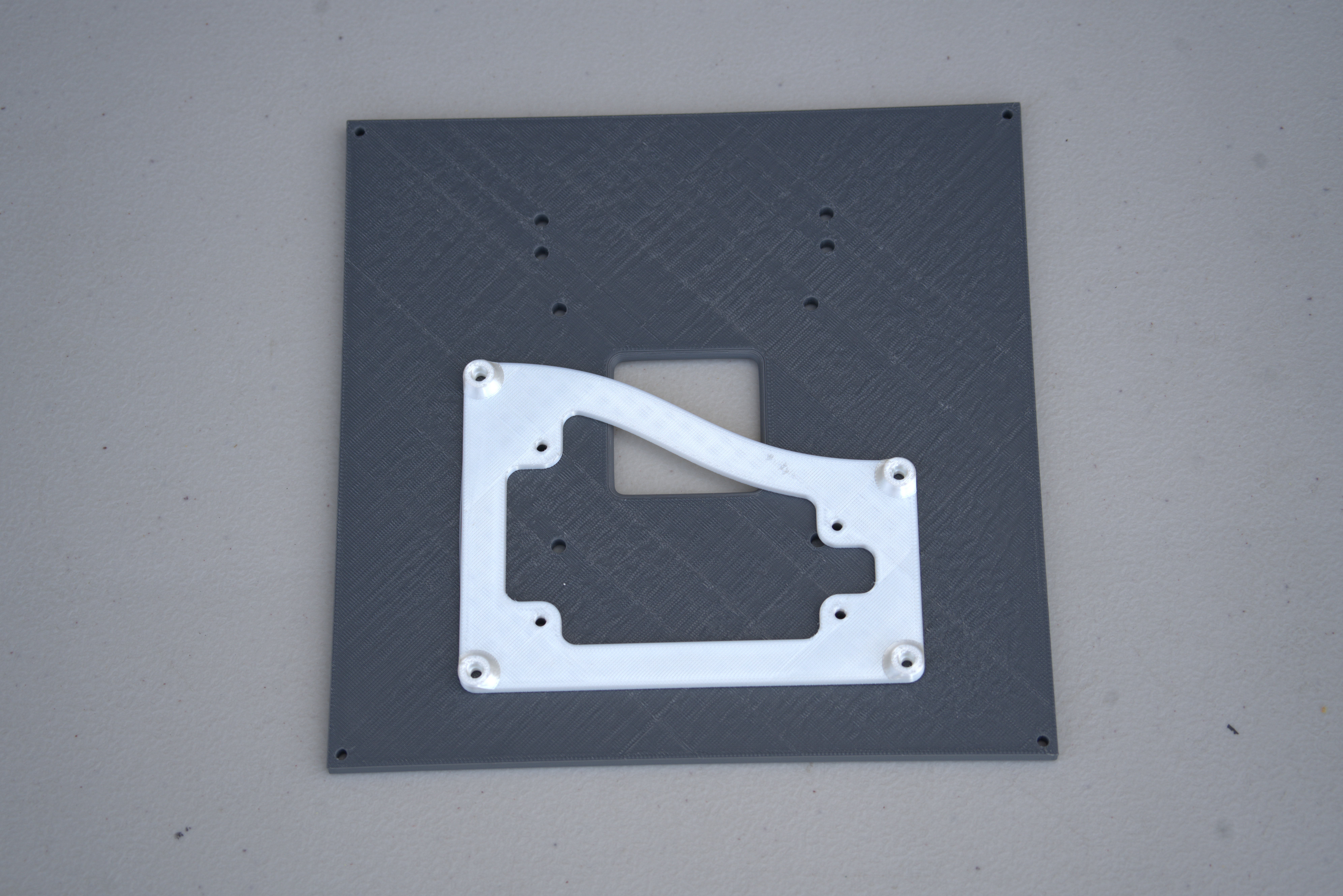
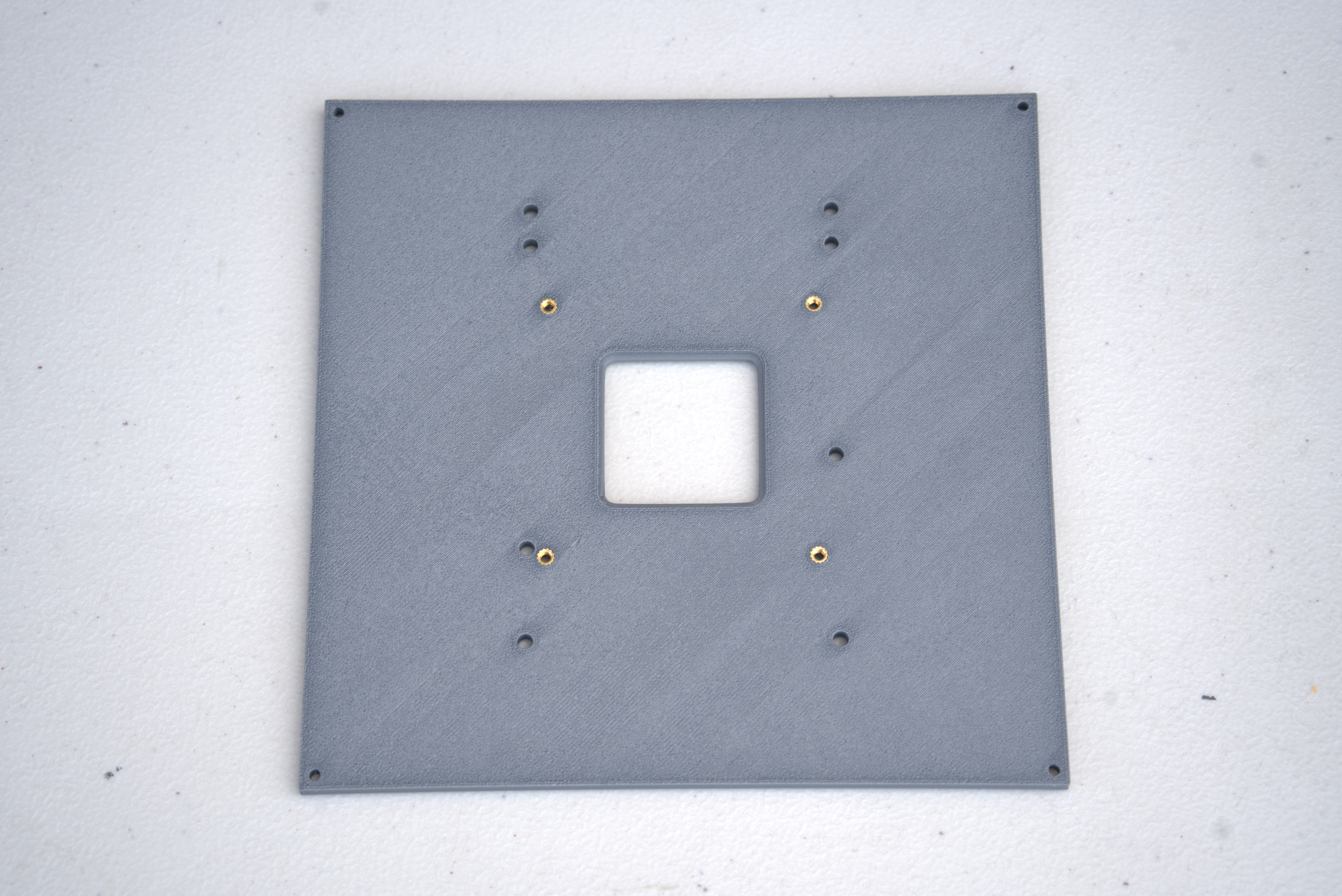
Once the PCB-mounting holes are aligned, install their inserts and the battery-mount inserts from that side. Install the module inserts from the opposite side.
The PCB mount also requires heat-set inserts in its outermost corners.
Step 2: Motors
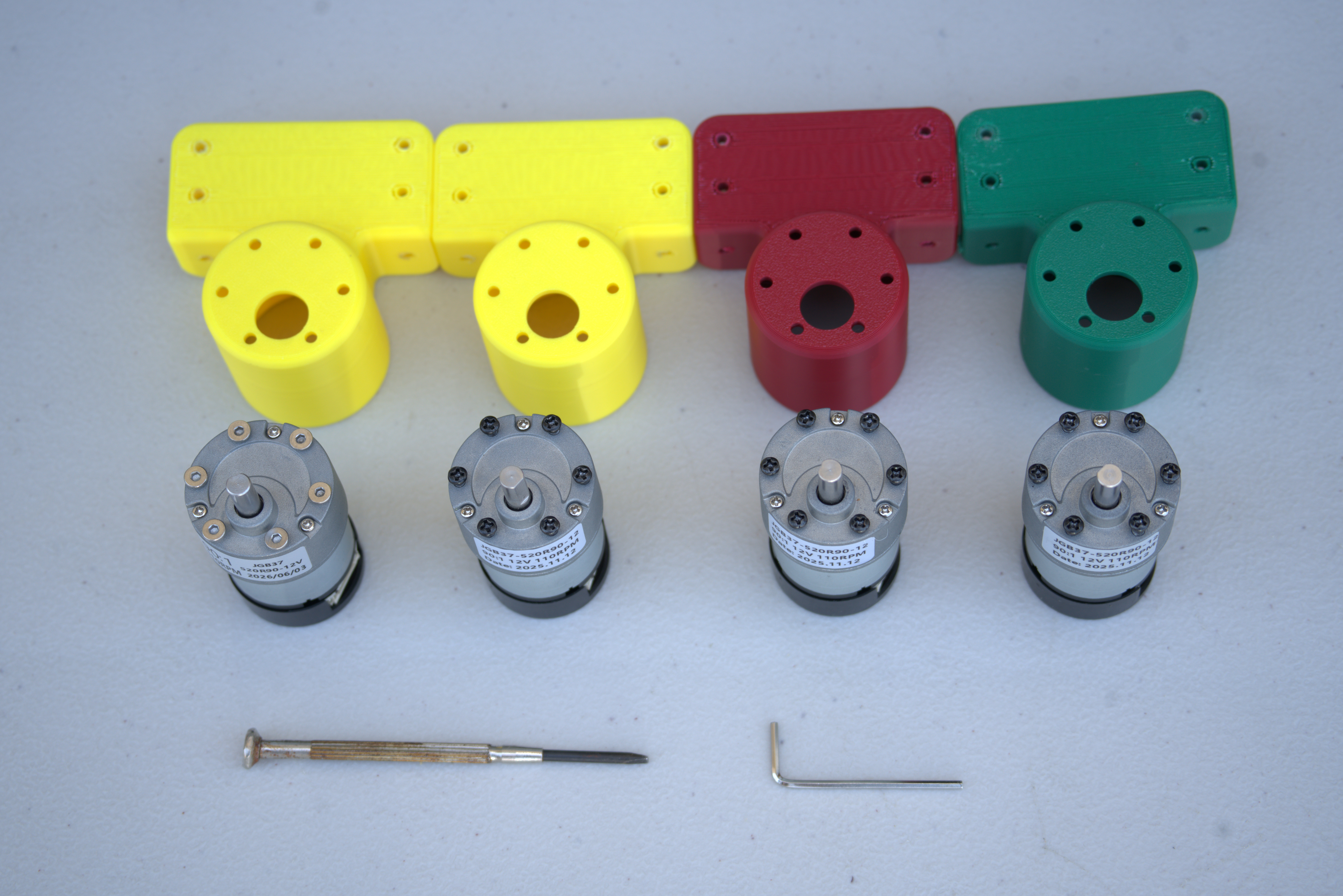
Install the motors in their mounts. Each motor requires six small M3 screws.
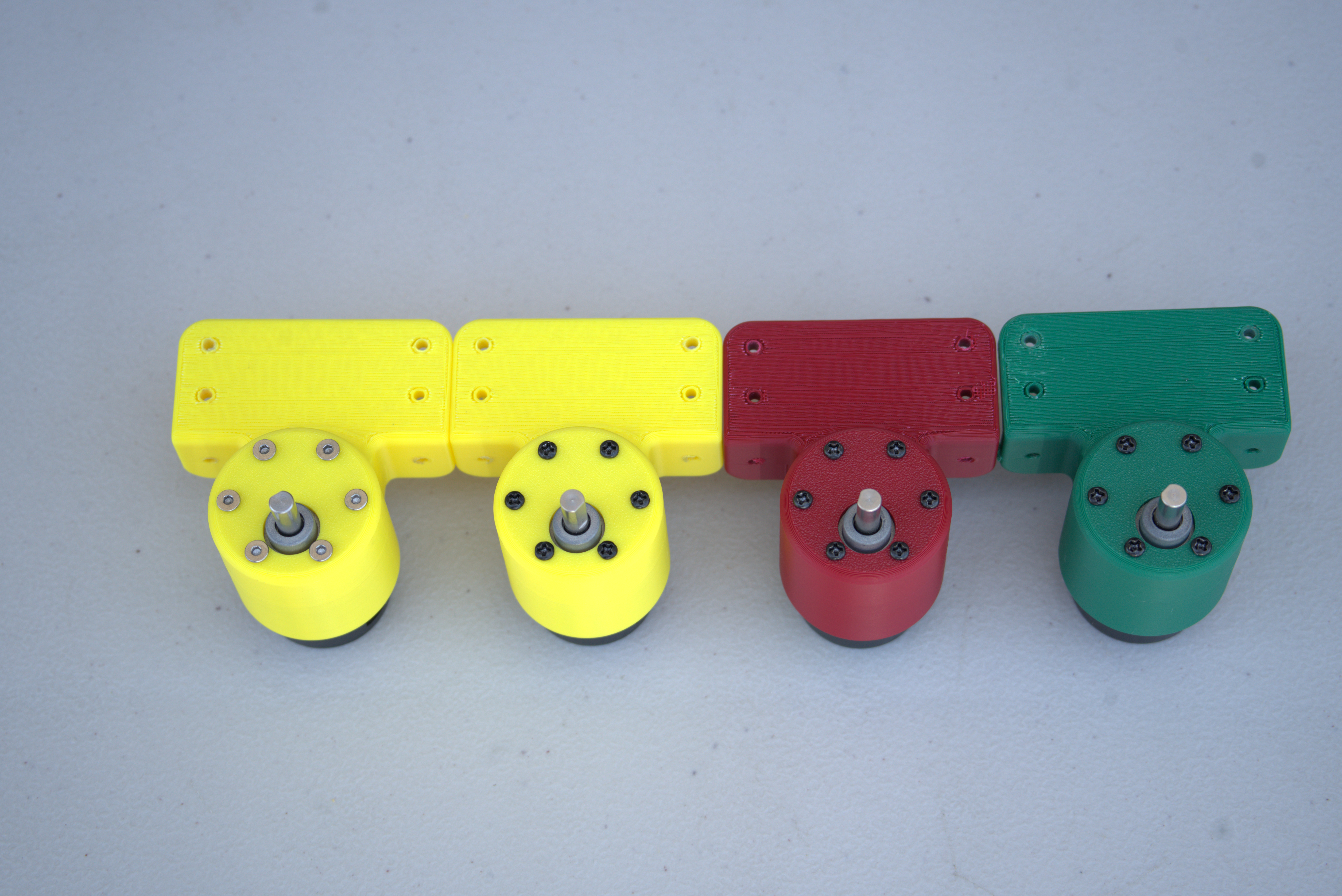
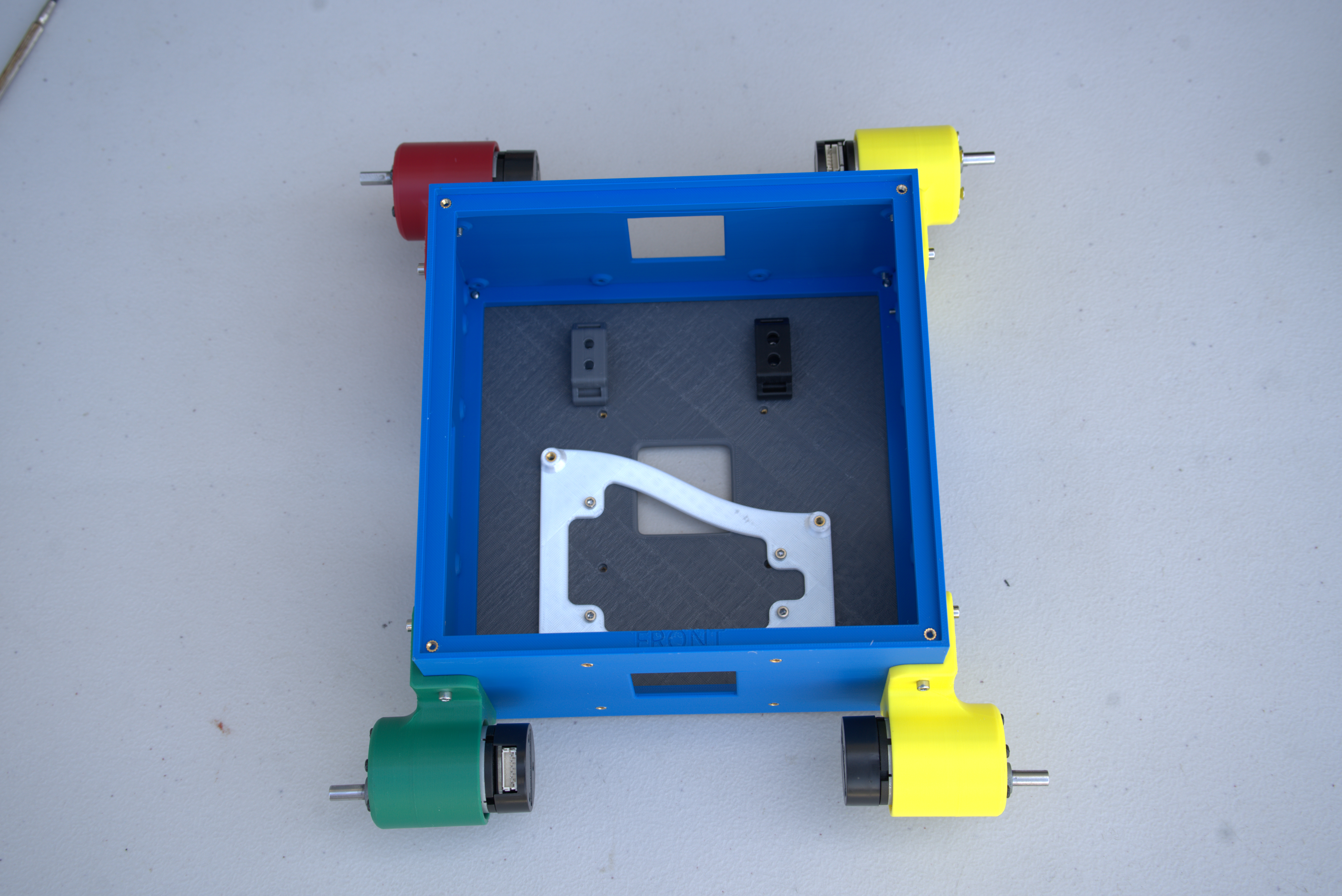
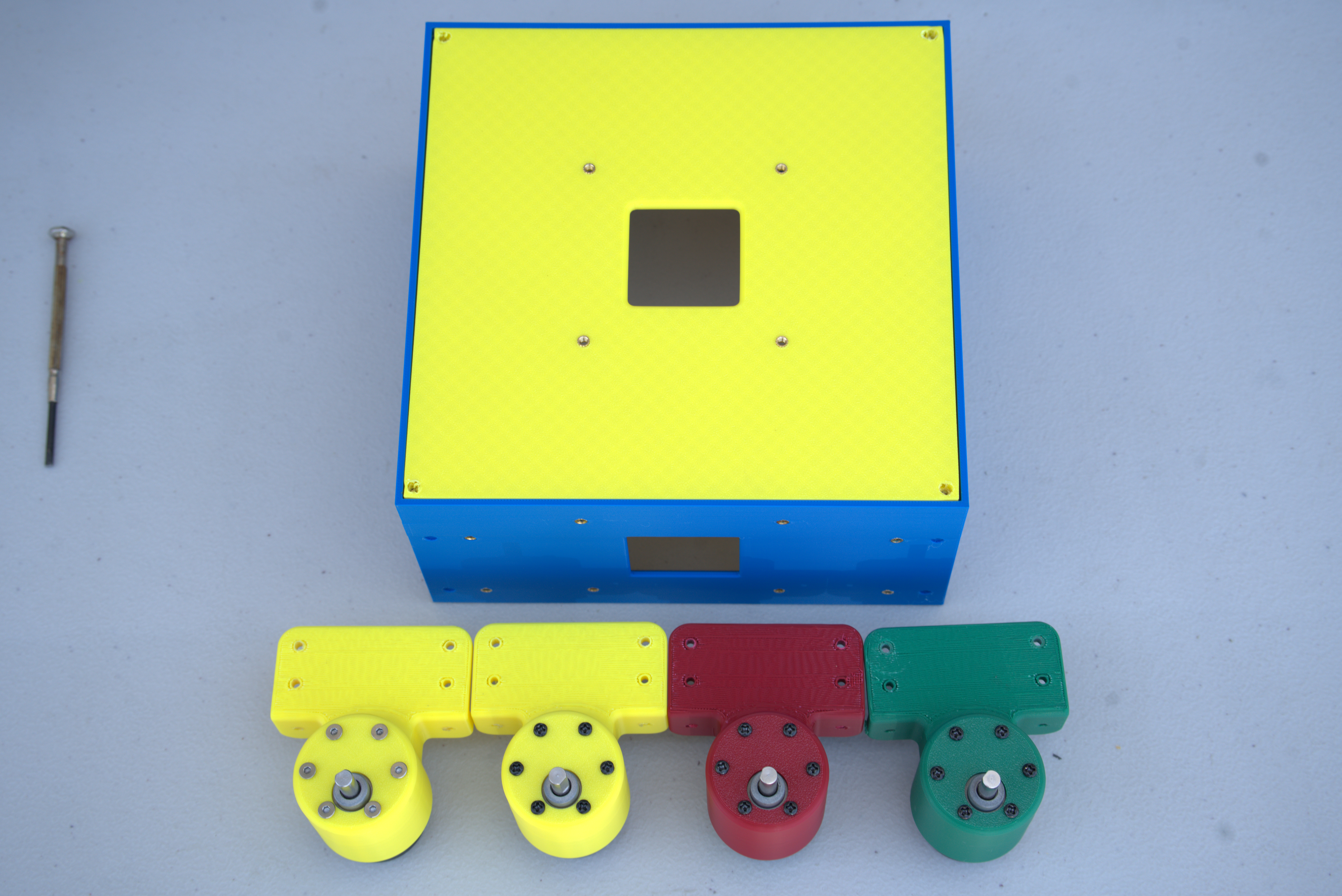
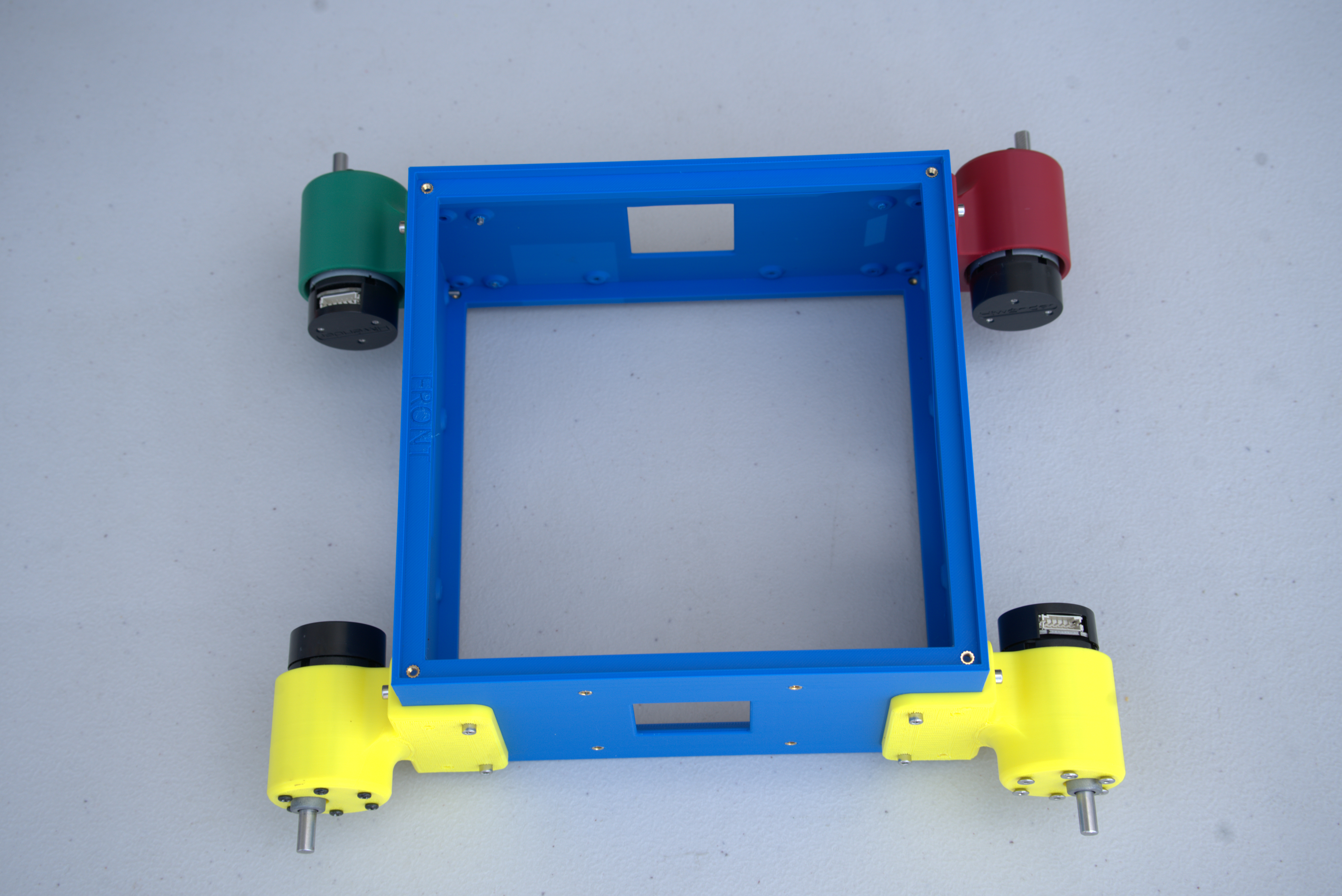
Attach the assembled motor mounts to the chassis.
Step 3: PCB
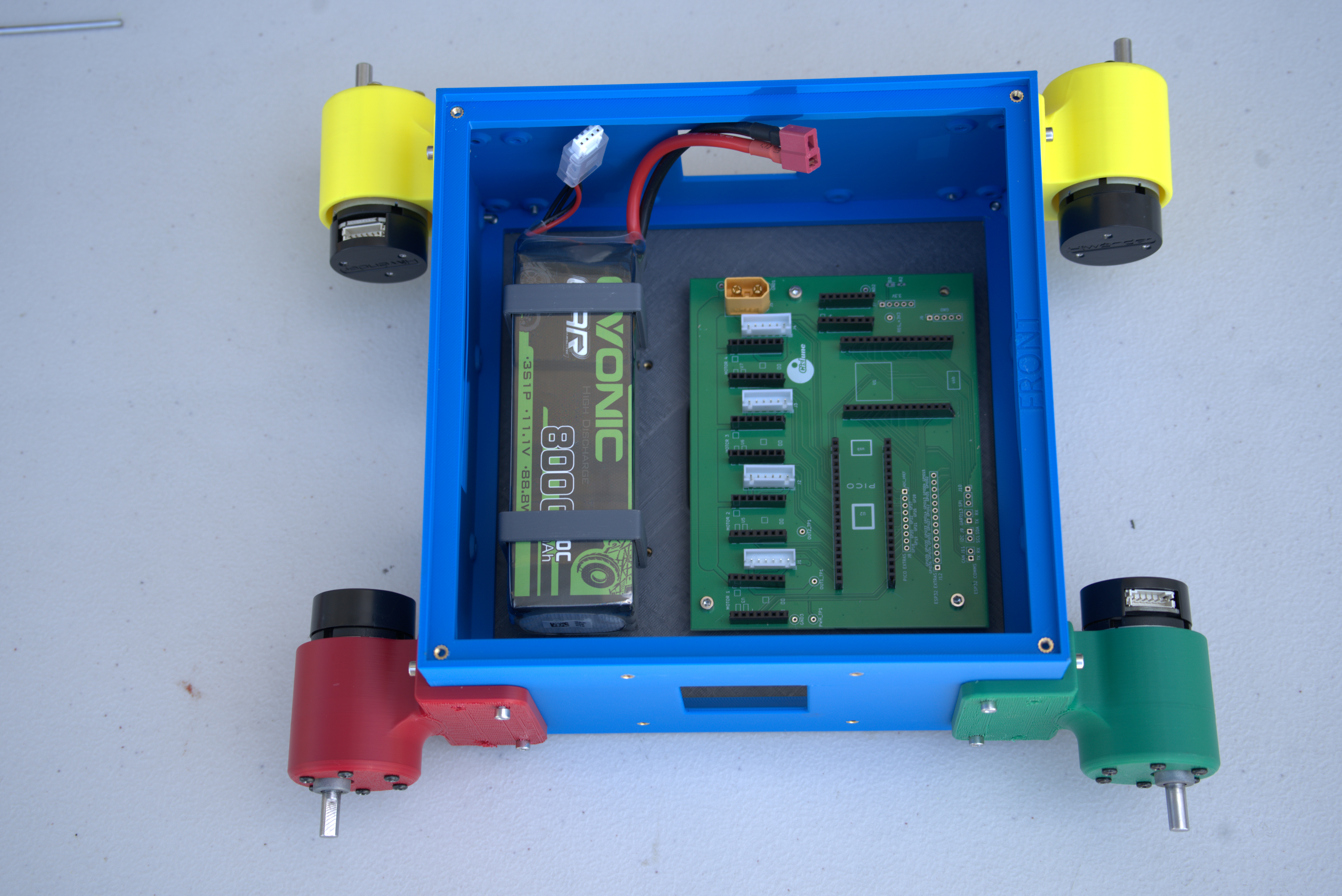
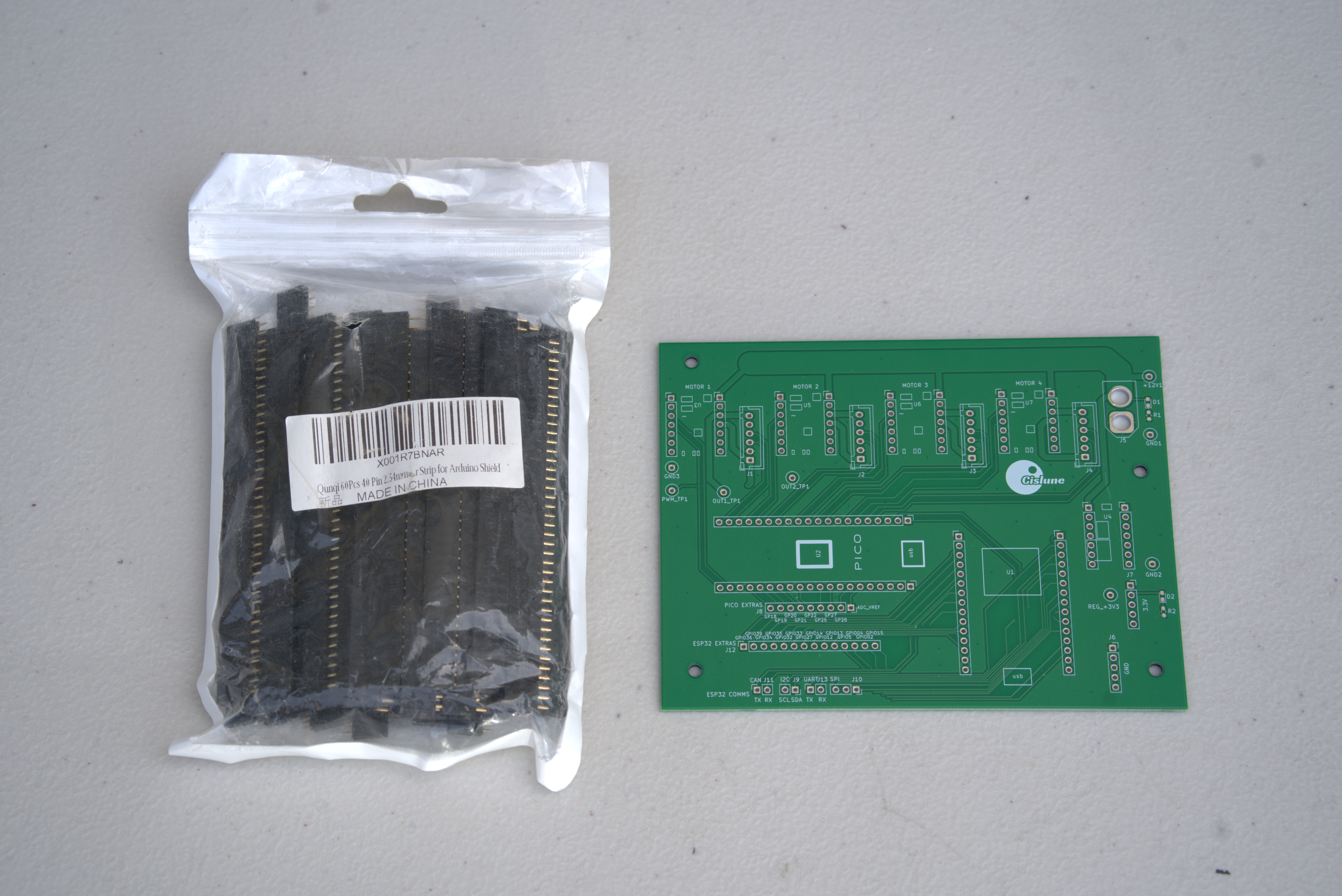
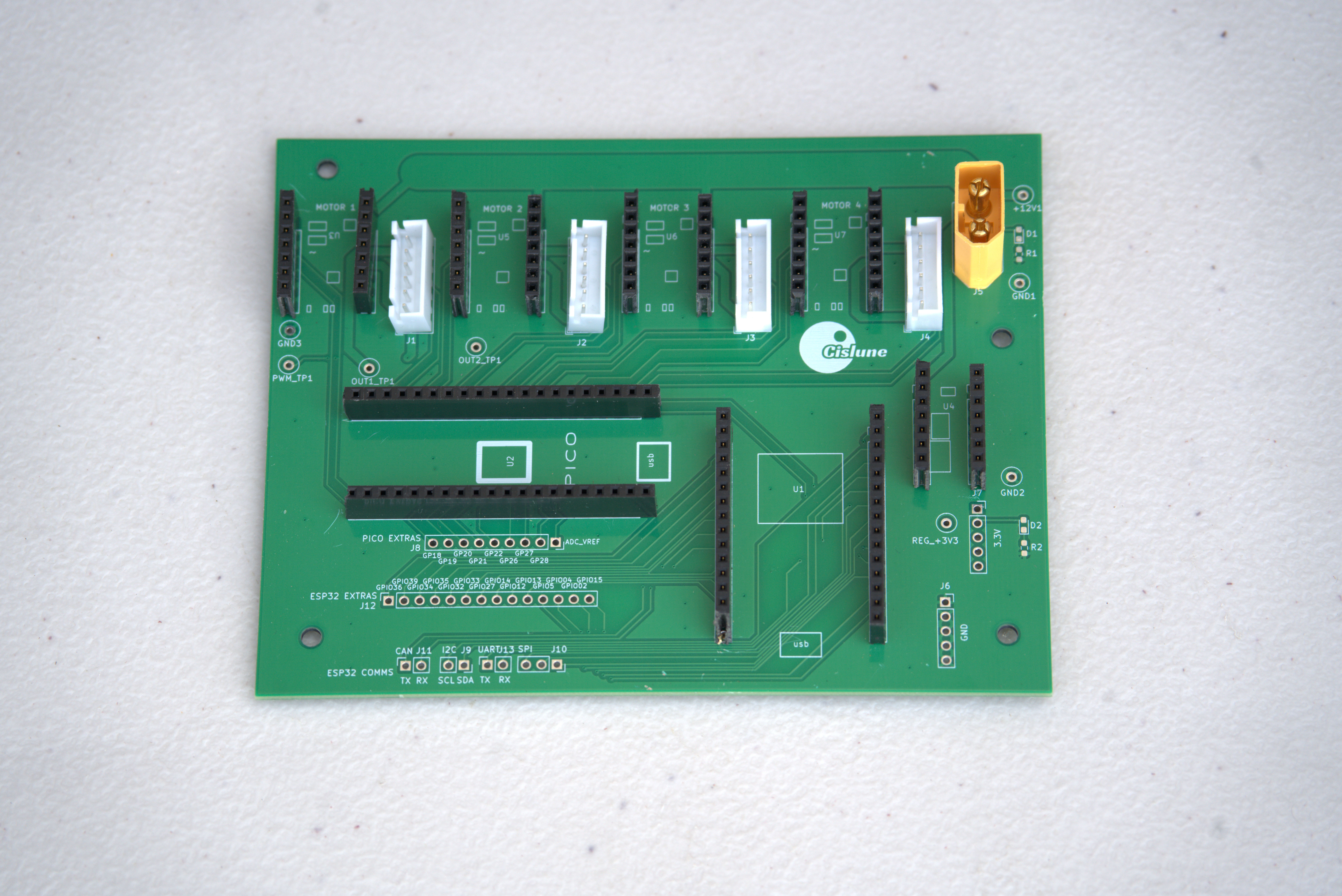
The PCB acts as a breakout board for the rover components. Install the required female headers, JST XH connectors, and XT60 connector, then solder them to the board.
Step 4: Final Assembly
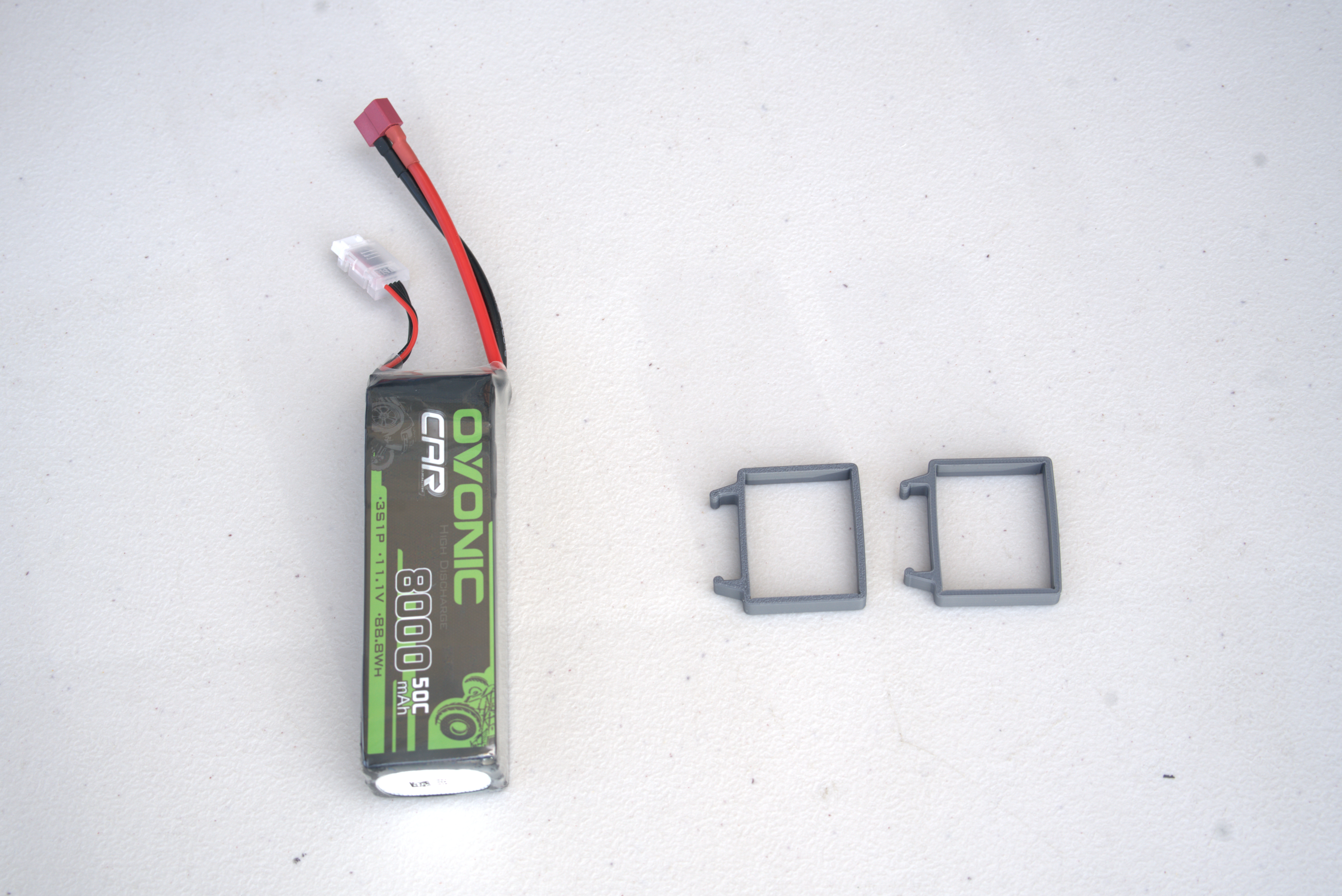
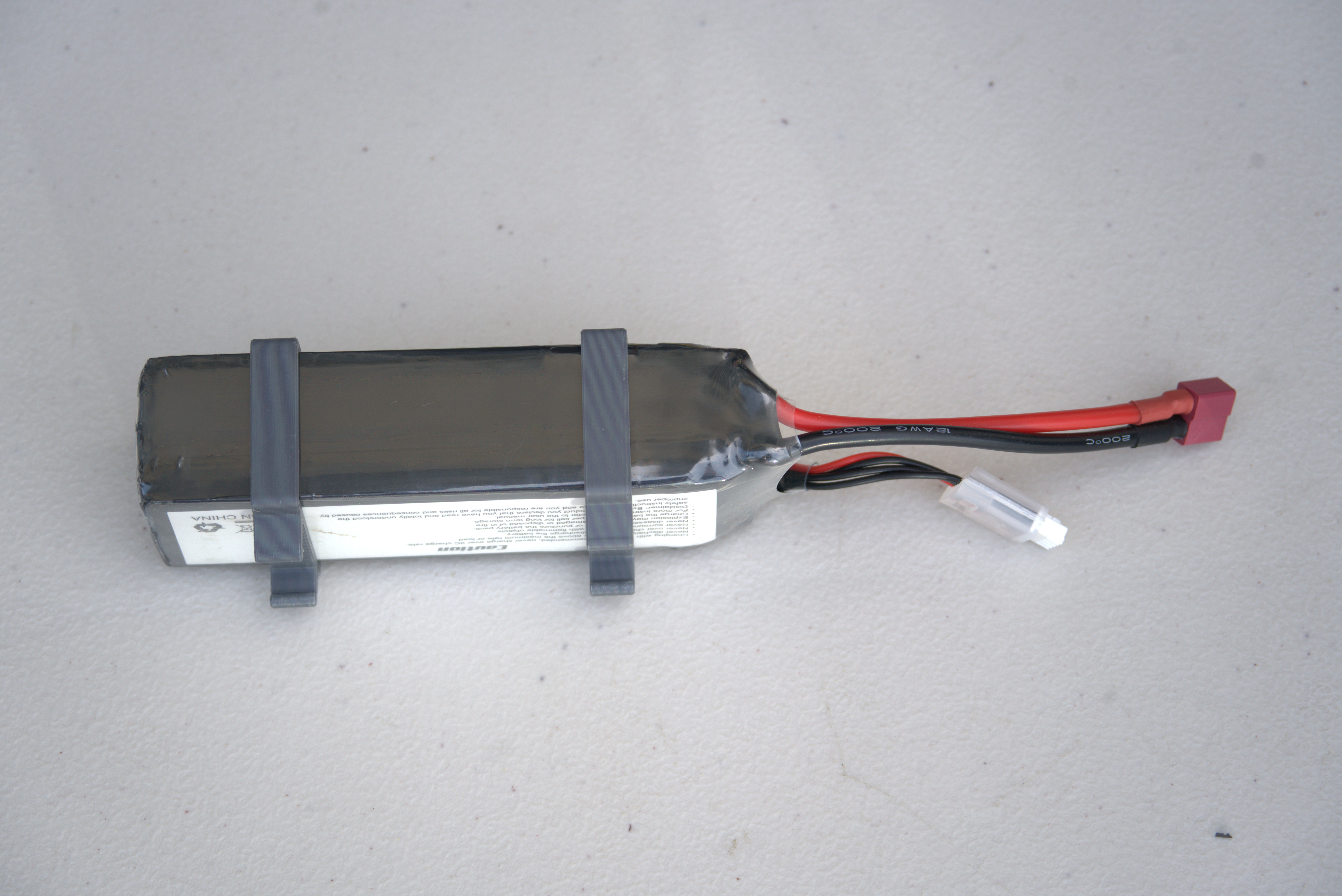
Install the battery clips, chassis plates, and remaining components as shown below.